Arduino UNO R3 與光敏電阻感測器
紅外線循跡感測器 (IR Tracker Sensor)
/*
KSM017
入射光強,電阻減小,入射光弱,電阻增大
1、VCC 電源3.3-5V
2、GND 接地
3、DO TTL開關信号输出 數位輸出(0 or 1)
4、AO 模擬信號输出 類比輸出(電壓)
*/
int iAo = A1;
int iDo = 7;
void setup() {
// put your setup code here, to run once:
Serial.begin(9600);
pinMode(iDo,INPUT);
pinMode(iAo,INPUT);
}
void loop() {
// put your main code here, to run repeatedly:
int pr = analogRead(iAo);
//int pr2 = analogRead(iDo);
Serial.print("Dgt=");
Serial.print(digitalRead(iDo));
Serial.print(" | ");
Serial.print("Alg=");
Serial.println(pr);
//int sensorValue = analogRead(1);
//float Rsensor=(float)(1023-sensorValue)*10/sensorValue;
//Serial.println(Rsensor);
delay(1000);
}
2015年9月18日 星期五


2015年9月13日 星期日
Arduino UNO R3 與 L298N馬達驅動板 測試
Arduino UNO R3 與 L298N馬達驅動板的配合是蠻多人使用的方式,一開始我也是照網路上大家的接法但是馬達就是不動作,後來又爬文爬好久才知道自己的錯誤點(就是沒把L298N與Arduino 板用GRD串接起來)因此怎麼測試馬達就是不動作。
另外要注意的一點就是你用L298N接2個DC馬達,其中ENA或ENB接在D9、D10腳位控制PWM輸出時,如果又用上Servo時會發現D9、D10失效
我之前組裝尋跡自走車時用L298N控制2顆DC馬達可以走得穩穩的,後來加上一顆SG90 Servo9G腳位接在D12時其中一顆DC馬達ENA就會發生不動作,原以為是電壓不足就外接電源但ENA依然不動作,上網查資料才知道當使用Servo.h函式庫時D9 與 D10 腳位的 PWM 功能就會被停用,所以ENA PWM失效解決辦法就是ENA PWM不要接D9或 D10
Servo伺服器雖然使用了 PWM 訊號來控制馬達轉動,不過,這不表示要使用 Arduino 的 PWM 腳位,只不過根據 Servo library 的說明,除了 Arduino Mega 之外,如果使用了 Arduino 的 Servo 程式庫,D9 與 D10 腳位的 PWM 功能就會被停用。(網路資源) (網路資源)
原文如下
The Servo library supports up to 12 motors on most Arduino boards and 48 on the Arduino Mega. On boards other than the Mega, use of the library disables analogWrite() (PWM) functionality on pins 9 and 10, whether or not there is a Servo on those pins. On the Mega, up to 12 servos can be used without interfering with PWM functionality; use of 12 to 23 motors will disable PWM on pins 11 and 12.
在Arduino板子中的第3、5、6、9、10、11腳可做PWM輸出,其頻率大都為490Hz,而在Uno板子,第5、6腳的頻率約980Hz
L298N使用方式
網路上另一篇文章
這篇就是解決問題的文章
/*
首先來看電源的接法,電源的接法可分成三種,第一種是只提供一組外部電源+12V。
將+12V電源的正負分別接到+12V與GND這兩個插座,同時將+12V上方的Jumper短路,
此時+12V會連接到7805,然後降壓成5V,提供給板子上的IC使用。不需要將5V接到Arduino的板子取得5V電源。
第二種接法同第一種接法,但將5V接到Arduino板子的5V,提供5V給Arduino板,所以Arduino板不需要另外再接5V電源來供電。
第三種接法則是將+12V上方的Jumper拔起來,不透過7805來產生5V,
但必須將+5V的插座接到Arduino的5V,也就是從Arduino提供5V給L298N使用。
以上三種接法,不論哪一種接法,一定要將GND插座與Arduino的GND相連,如此`才有共同的零電壓準位。
*/
/*
int value;
int dir;
void setup() {
pinMode(3, OUTPUT); //接到ENA
pinMode(4, OUTPUT); //接到N1
pinMode(5, OUTPUT); //接到N2
digitalWrite(4, HIGH); //設定馬達正轉
digitalWrite(5, LOW);
value= 255; //PWM輸出值
dir = -1; //value值的遞增或遞減
}
void loop() {
value= value+ dir;
if (value< 80) //當value值小於80時,馬達不會轉,所以dir改成遞增(如果使用3V馬達 上下限值不能大於50~150, 5V 80~255)
dir = 1;
else if (value>= 255) //當value值為最大255時,dir改成遞減
dir = -1;
analogWrite(3, value);
delay(200);
}
*/
程式碼如下:
//也可以用 Analog A0 ~ A5
//Digital PWM 3、5、6、9、10、11
const int motorIn1=5;
const int motorIn2=6;
const int motorIn3=9;
const int motorIn4=10;
void setup() {
pinMode(motorIn1, OUTPUT); //接到N5
pinMode(motorIn2, OUTPUT); //接到N6
pinMode(motorIn3, OUTPUT); //接到N9
pinMode(motorIn4, OUTPUT); //接到N10
}
void loop() {
//正轉
for(int i=150;i<255 i="" p=""> analogWrite(motorIn1,i);
analogWrite(motorIn2,0);
analogWrite(motorIn3,i);
analogWrite(motorIn4,0);
delay(500);
}
analogWrite(motorIn1,0);
analogWrite(motorIn2,0);
analogWrite(motorIn3,0);
analogWrite(motorIn4,0);
delay(2000);
//反轉
for(int i=150;i<255 i="" p=""> analogWrite(motorIn1,0);
analogWrite(motorIn2,i);
analogWrite(motorIn3,0);
analogWrite(motorIn4,i);
delay(500);
}
analogWrite(motorIn1,0);
analogWrite(motorIn2,0);
analogWrite(motorIn3,0);
analogWrite(motorIn4,0);
delay(2000);
}
另外要注意的一點就是你用L298N接2個DC馬達,其中ENA或ENB接在D9、D10腳位控制PWM輸出時,如果又用上Servo時會發現D9、D10失效
我之前組裝尋跡自走車時用L298N控制2顆DC馬達可以走得穩穩的,後來加上一顆SG90 Servo9G腳位接在D12時其中一顆DC馬達ENA就會發生不動作,原以為是電壓不足就外接電源但ENA依然不動作,上網查資料才知道當使用Servo.h函式庫時D9 與 D10 腳位的 PWM 功能就會被停用,所以ENA PWM失效解決辦法就是ENA PWM不要接D9或 D10
Servo伺服器雖然使用了 PWM 訊號來控制馬達轉動,不過,這不表示要使用 Arduino 的 PWM 腳位,只不過根據 Servo library 的說明,除了 Arduino Mega 之外,如果使用了 Arduino 的 Servo 程式庫,D9 與 D10 腳位的 PWM 功能就會被停用。(網路資源) (網路資源)
原文如下
The Servo library supports up to 12 motors on most Arduino boards and 48 on the Arduino Mega. On boards other than the Mega, use of the library disables analogWrite() (PWM) functionality on pins 9 and 10, whether or not there is a Servo on those pins. On the Mega, up to 12 servos can be used without interfering with PWM functionality; use of 12 to 23 motors will disable PWM on pins 11 and 12.
在Arduino板子中的第3、5、6、9、10、11腳可做PWM輸出,其頻率大都為490Hz,而在Uno板子,第5、6腳的頻率約980Hz
L298N使用方式
網路上另一篇文章
這篇就是解決問題的文章
/*
首先來看電源的接法,電源的接法可分成三種,第一種是只提供一組外部電源+12V。
將+12V電源的正負分別接到+12V與GND這兩個插座,同時將+12V上方的Jumper短路,
此時+12V會連接到7805,然後降壓成5V,提供給板子上的IC使用。不需要將5V接到Arduino的板子取得5V電源。
第二種接法同第一種接法,但將5V接到Arduino板子的5V,提供5V給Arduino板,所以Arduino板不需要另外再接5V電源來供電。
第三種接法則是將+12V上方的Jumper拔起來,不透過7805來產生5V,
但必須將+5V的插座接到Arduino的5V,也就是從Arduino提供5V給L298N使用。
以上三種接法,不論哪一種接法,一定要將GND插座與Arduino的GND相連,如此`才有共同的零電壓準位。
*/
/*
int value;
int dir;
void setup() {
pinMode(3, OUTPUT); //接到ENA
pinMode(4, OUTPUT); //接到N1
pinMode(5, OUTPUT); //接到N2
digitalWrite(4, HIGH); //設定馬達正轉
digitalWrite(5, LOW);
value= 255; //PWM輸出值
dir = -1; //value值的遞增或遞減
}
void loop() {
value= value+ dir;
if (value< 80) //當value值小於80時,馬達不會轉,所以dir改成遞增(如果使用3V馬達 上下限值不能大於50~150, 5V 80~255)
dir = 1;
else if (value>= 255) //當value值為最大255時,dir改成遞減
dir = -1;
analogWrite(3, value);
delay(200);
}
*/
程式碼如下:
//也可以用 Analog A0 ~ A5
//Digital PWM 3、5、6、9、10、11
const int motorIn1=5;
const int motorIn2=6;
const int motorIn3=9;
const int motorIn4=10;
void setup() {
pinMode(motorIn1, OUTPUT); //接到N5
pinMode(motorIn2, OUTPUT); //接到N6
pinMode(motorIn3, OUTPUT); //接到N9
pinMode(motorIn4, OUTPUT); //接到N10
}
void loop() {
//正轉
for(int i=150;i<255 i="" p=""> analogWrite(motorIn1,i);
analogWrite(motorIn2,0);
analogWrite(motorIn3,i);
analogWrite(motorIn4,0);
delay(500);
}
analogWrite(motorIn1,0);
analogWrite(motorIn2,0);
analogWrite(motorIn3,0);
analogWrite(motorIn4,0);
delay(2000);
//反轉
for(int i=150;i<255 i="" p=""> analogWrite(motorIn1,0);
analogWrite(motorIn2,i);
analogWrite(motorIn3,0);
analogWrite(motorIn4,i);
delay(500);
}
analogWrite(motorIn1,0);
analogWrite(motorIn2,0);
analogWrite(motorIn3,0);
analogWrite(motorIn4,0);
delay(2000);
}
2015年6月24日 星期三
Arduino Color Sensor 顏色感應器 TCS230
Arduino Color Sensor 顏色感應器 TCS230
Pin 腳接法

#include
#define S0 6 // Please notice the Pin's define
#define S1 5
#define S2 4
#define S3 3
#define OUT 2
int g_count = 0; // count the frequecy
int g_array[3]; // store the RGB value
int g_flag = 0; // filter of RGB queue
float g_SF[3]; // save the RGB Scale factor
// Init TSC230 and setting Frequency.
void TSC_Init()
{
pinMode(S0, OUTPUT);
pinMode(S1, OUTPUT);
pinMode(S2, OUTPUT);
pinMode(S3, OUTPUT);
pinMode(OUT, INPUT);
digitalWrite(S0, LOW); // OUTPUT FREQUENCY SCALING 2%
digitalWrite(S1, HIGH);
}
// Select the filter color
void TSC_FilterColor(int Level01, int Level02)
{
if(Level01 != 0)
Level01 = HIGH;
if(Level02 != 0)
Level02 = HIGH;
digitalWrite(S2, Level01);
digitalWrite(S3, Level02);
}
void TSC_Count()
{
g_count ++ ;
}
void TSC_Callback()
{
switch(g_flag)
{
case 0:
Serial.println("->WB Start");
TSC_WB(LOW, LOW); //Filter without Red
break;
case 1:
Serial.print("->Frequency R=");
Serial.println(g_count);
g_array[0] = g_count;
TSC_WB(HIGH, HIGH); //Filter without Green
break;
case 2:
Serial.print("->Frequency G=");
Serial.println(g_count);
g_array[1] = g_count;
TSC_WB(LOW, HIGH); //Filter without Blue
break;
case 3:
Serial.print("->Frequency B=");
Serial.println(g_count);
Serial.println("->WB End");
g_array[2] = g_count;
TSC_WB(HIGH, LOW); //Clear(no filter)
break;
default:
g_count = 0;
break;
}
}
void TSC_WB(int Level0, int Level1) //White Balance
{
g_count = 0;
g_flag ++;
TSC_FilterColor(Level0, Level1);
Timer1.setPeriod(1000000); // set 1s period
}
void setup()
{
TSC_Init();
Serial.begin(9600);
Timer1.initialize(); // defaulte is 1s
Timer1.attachInterrupt(TSC_Callback);
attachInterrupt(0, TSC_Count, RISING);
delay(4000);
for(int i=0; i<3 i="" p=""> Serial.println(g_array[i]);
g_SF[0] = 255.0/ g_array[0]; //R Scale factor
g_SF[1] = 255.0/ g_array[1] ; //G Scale factor
g_SF[2] = 255.0/ g_array[2] ; //B Scale factor
Serial.println(g_SF[0]);
Serial.println(g_SF[1]);
Serial.println(g_SF[2]);
}
void loop()
{
g_flag = 0;
for(int i=0; i<3 i="" p=""> Serial.println(int(g_array[i] * g_SF[i]));
delay(4000);
}
Pin 腳接法

#include
#define S0 6 // Please notice the Pin's define
#define S1 5
#define S2 4
#define S3 3
#define OUT 2
int g_count = 0; // count the frequecy
int g_array[3]; // store the RGB value
int g_flag = 0; // filter of RGB queue
float g_SF[3]; // save the RGB Scale factor
// Init TSC230 and setting Frequency.
void TSC_Init()
{
pinMode(S0, OUTPUT);
pinMode(S1, OUTPUT);
pinMode(S2, OUTPUT);
pinMode(S3, OUTPUT);
pinMode(OUT, INPUT);
digitalWrite(S0, LOW); // OUTPUT FREQUENCY SCALING 2%
digitalWrite(S1, HIGH);
}
// Select the filter color
void TSC_FilterColor(int Level01, int Level02)
{
if(Level01 != 0)
Level01 = HIGH;
if(Level02 != 0)
Level02 = HIGH;
digitalWrite(S2, Level01);
digitalWrite(S3, Level02);
}
void TSC_Count()
{
g_count ++ ;
}
void TSC_Callback()
{
switch(g_flag)
{
case 0:
Serial.println("->WB Start");
TSC_WB(LOW, LOW); //Filter without Red
break;
case 1:
Serial.print("->Frequency R=");
Serial.println(g_count);
g_array[0] = g_count;
TSC_WB(HIGH, HIGH); //Filter without Green
break;
case 2:
Serial.print("->Frequency G=");
Serial.println(g_count);
g_array[1] = g_count;
TSC_WB(LOW, HIGH); //Filter without Blue
break;
case 3:
Serial.print("->Frequency B=");
Serial.println(g_count);
Serial.println("->WB End");
g_array[2] = g_count;
TSC_WB(HIGH, LOW); //Clear(no filter)
break;
default:
g_count = 0;
break;
}
}
void TSC_WB(int Level0, int Level1) //White Balance
{
g_count = 0;
g_flag ++;
TSC_FilterColor(Level0, Level1);
Timer1.setPeriod(1000000); // set 1s period
}
void setup()
{
TSC_Init();
Serial.begin(9600);
Timer1.initialize(); // defaulte is 1s
Timer1.attachInterrupt(TSC_Callback);
attachInterrupt(0, TSC_Count, RISING);
delay(4000);
for(int i=0; i<3 i="" p=""> Serial.println(g_array[i]);
g_SF[0] = 255.0/ g_array[0]; //R Scale factor
g_SF[1] = 255.0/ g_array[1] ; //G Scale factor
g_SF[2] = 255.0/ g_array[2] ; //B Scale factor
Serial.println(g_SF[0]);
Serial.println(g_SF[1]);
Serial.println(g_SF[2]);
}
void loop()
{
g_flag = 0;
for(int i=0; i<3 i="" p=""> Serial.println(int(g_array[i] * g_SF[i]));
delay(4000);
}
2015年6月23日 星期二
Arduino 與 步進馬達28BYJ-48 5v DC+ARDUINO MOTOR SHIELD L293D 驅動板
Arduino 與 步進馬達28BYJ-48 5v DC+ARDUINO MOTOR SHIELD L293D驅動板 實做
網路資源
零件清單
1.Arduino UNO
2.步進馬達28BYJ-48 5v DC
3. 驅動板
#include
#define STEPS 200 //定義步進馬達每圈的步數
//steps:代表馬達轉完一圈需要多少步數。如果馬達上有標示每步的度數,
//將360除以這個角度,就可以得到所需要的步數(例如:360/3.6=100)。(int)
//如果步進馬達只會往一個方向轉動,不會反轉把 pin 2 與 pin3 要交換接
Stepper stepper(STEPS, 9, 10, 11, 12);
void setup(){
stepper.setSpeed(140); // 將馬達的速度設定成140RPM 最大 150~160
}
void loop(){
stepper.step(1600);//正8圈
delay(1000);
stepper.step(-1600);//反8圈
delay(1000);
}
Part 2
1.Arduino UNO
2.直流馬達 DC Motor
3.ARDUINO MOTOR SHIELD L293D
網路資源 網路資源2 網路資源3 網路資源4


在Arduino UNO 對應腳位Pine
#define MOTO_M1_A 2
#define MOTO_M1_B 3
#define MOTO_M2_A 1
#define MOTO_M2_B 4
#define MOTO_M3_A 5
#define MOTO_M3_B 7
#define MOTO_M4_A 0
#define MOTO_M4_B 6
// Arduino pins for the PWM signals.
#define MOTOR1_PWM 11
#define MOTOR2_PWM 3
#define MOTOR3_PWM 6
#define MOTOR4_PWM 5
#define SERVO1_PWM 10
#define SERVO2_PWM 9
//使用直流馬達範例 DC Motor
//使用步進馬達 Step Motor

`stepsPerRevolution` 必須設定為你的馬達實際上一圈會有多少步,如果是 28BYJ-48 5V DC 的話,規格上寫著,步進角為 `5.625 / 64`,因此這馬達轉一圈需要的步數是 `360 / (5.625 / 64)`,也就是 `4096` 步,這是一/二相激磁才會有的步數,Stepper 程式庫原始碼它是採二相激磁的實作方式,因此,使用這個 Stepper 程式庫實際上要設的 `stepsPerRevolution` 是 `2048` 步
PWR Jumper 短路(套上)的話會對 Arduino UNO 板供電5V
#include
#include
#define SERVO1_PWM 10
#define SERVO2_PWM 9
double passos_total = 2048; //Numero de passos para 1 rotacao total
int porta_motor = 2; //1 para motor em M1/M2 e 2 para motor em M3/M4
int angulo = 30; //Angulo de rotacao do eixo
double numero_de_passos = 0; //Armazena o numero de passos que o motor vai girar
AF_Stepper arduino(passos_total, porta_motor); //Define os parametros do motor
Servo servo_1;
void setup()
{
arduino.setSpeed(10); //Define a velocidade de rotacao
Serial.begin(9600);
servo_1.attach(SERVO1_PWM);
}
void loop()
{
//Calcula a quantidade de passos, baseado no angulo determinado
numero_de_passos = angulo / (360 / passos_total);
//170.67/步
servo_1.write(0);
delay(1000);
servo_1.write(180);
delay(2000);
//Mostra no serial monitor o numero de passos calculados
Serial.println(numero_de_passos);
//Move o motor. Use FORWARD para sentido horario,
//BACKWARD para anti-horario
for(int i=0;i<=5;i++){
arduino.step(numero_de_passos, FORWARD, SINGLE);
arduino.release();
}
delay(2000);
for(int i=0;i<=5;i++){
arduino.step(numero_de_passos, BACKWARD, SINGLE);
arduino.release();
}
delay(2000);
}
//---------------------------------------------------------
#include
AF_Stepper motor(48, 2); //48表示每圈的步數(360度/步距角,48的步距角為7.5度)
//2表示第二路步進電機(共支持兩路)
網路資源
零件清單
1.Arduino UNO
2.步進馬達28BYJ-48 5v DC
3. 驅動板
#include
#define STEPS 200 //定義步進馬達每圈的步數
//steps:代表馬達轉完一圈需要多少步數。如果馬達上有標示每步的度數,
//將360除以這個角度,就可以得到所需要的步數(例如:360/3.6=100)。(int)
//如果步進馬達只會往一個方向轉動,不會反轉把 pin 2 與 pin3 要交換接
Stepper stepper(STEPS, 9, 10, 11, 12);
void setup(){
stepper.setSpeed(140); // 將馬達的速度設定成140RPM 最大 150~160
}
void loop(){
stepper.step(1600);//正8圈
delay(1000);
stepper.step(-1600);//反8圈
delay(1000);
}
Part 2
1.Arduino UNO
2.直流馬達 DC Motor
3.ARDUINO MOTOR SHIELD L293D
網路資源 網路資源2 網路資源3 網路資源4


在Arduino UNO 對應腳位Pine
#define MOTO_M1_A 2
#define MOTO_M1_B 3
#define MOTO_M2_A 1
#define MOTO_M2_B 4
#define MOTO_M3_A 5
#define MOTO_M3_B 7
#define MOTO_M4_A 0
#define MOTO_M4_B 6
// Arduino pins for the PWM signals.
#define MOTOR1_PWM 11
#define MOTOR2_PWM 3
#define MOTOR3_PWM 6
#define MOTOR4_PWM 5
#define SERVO1_PWM 10
#define SERVO2_PWM 9
//使用直流馬達範例 DC Motor
#include //呼叫該函式庫
AF_DCMotor motor(4, MOTOR12_64KHZ); // AF_DCMotor 變數名稱(第幾個馬達控制, 頻率)
// Motor1 & Motor2 有這幾個頻率:
// MOTOR12_64KHZ, MOTOR12_8KHZ,
//MOTOR12_2KHZ, MOTOR12_1KHZ
//
// Motor3 & Motor4 有這幾個頻率:
// MOTOR12_64KHZ, MOTOR12_8KHZ, MOTOR12_1KHZ
//
void setup() {
Serial.begin(9600); // set up Serial library at 9600 bps
Serial.println("Motor test!");
motor.setSpeed(200); // set the speed to 200/255
}
void loop() {
Serial.print("tick");
motor.run(FORWARD); // turn it on going forward
delay(1000);
Serial.print("tock");
motor.run(BACKWARD); // the other way
delay(1000);
Serial.print("tack");
motor.run(RELEASE); // stopped
delay(1000);
}
AF_DCMotor motor(4, MOTOR12_64KHZ); // AF_DCMotor 變數名稱(第幾個馬達控制, 頻率)
// Motor1 & Motor2 有這幾個頻率:
// MOTOR12_64KHZ, MOTOR12_8KHZ,
//MOTOR12_2KHZ, MOTOR12_1KHZ
//
// Motor3 & Motor4 有這幾個頻率:
// MOTOR12_64KHZ, MOTOR12_8KHZ, MOTOR12_1KHZ
//
void setup() {
Serial.begin(9600); // set up Serial library at 9600 bps
Serial.println("Motor test!");
motor.setSpeed(200); // set the speed to 200/255
}
void loop() {
Serial.print("tick");
motor.run(FORWARD); // turn it on going forward
delay(1000);
Serial.print("tock");
motor.run(BACKWARD); // the other way
delay(1000);
Serial.print("tack");
motor.run(RELEASE); // stopped
delay(1000);
}
//使用步進馬達 Step Motor

`stepsPerRevolution` 必須設定為你的馬達實際上一圈會有多少步,如果是 28BYJ-48 5V DC 的話,規格上寫著,步進角為 `5.625 / 64`,因此這馬達轉一圈需要的步數是 `360 / (5.625 / 64)`,也就是 `4096` 步,這是一/二相激磁才會有的步數,Stepper 程式庫原始碼它是採二相激磁的實作方式,因此,使用這個 Stepper 程式庫實際上要設的 `stepsPerRevolution` 是 `2048` 步
PWR Jumper 短路(套上)的話會對 Arduino UNO 板供電5V
#include
#include
#define SERVO1_PWM 10
#define SERVO2_PWM 9
double passos_total = 2048; //Numero de passos para 1 rotacao total
int porta_motor = 2; //1 para motor em M1/M2 e 2 para motor em M3/M4
int angulo = 30; //Angulo de rotacao do eixo
double numero_de_passos = 0; //Armazena o numero de passos que o motor vai girar
AF_Stepper arduino(passos_total, porta_motor); //Define os parametros do motor
Servo servo_1;
void setup()
{
arduino.setSpeed(10); //Define a velocidade de rotacao
Serial.begin(9600);
servo_1.attach(SERVO1_PWM);
}
void loop()
{
//Calcula a quantidade de passos, baseado no angulo determinado
numero_de_passos = angulo / (360 / passos_total);
//170.67/步
servo_1.write(0);
delay(1000);
servo_1.write(180);
delay(2000);
//Mostra no serial monitor o numero de passos calculados
Serial.println(numero_de_passos);
//Move o motor. Use FORWARD para sentido horario,
//BACKWARD para anti-horario
for(int i=0;i<=5;i++){
arduino.step(numero_de_passos, FORWARD, SINGLE);
arduino.release();
}
delay(2000);
for(int i=0;i<=5;i++){
arduino.step(numero_de_passos, BACKWARD, SINGLE);
arduino.release();
}
delay(2000);
}
//---------------------------------------------------------
#include
AF_Stepper motor(48, 2); //48表示每圈的步數(360度/步距角,48的步距角為7.5度)
//2表示第二路步進電機(共支持兩路)
void setup() {
Serial.begin(9600); // set up Serial library at 9600 bps
Serial.println("Stepper test!");
motor.setSpeed(10); // 10 rpm
motor.step(100, FORWARD, SINGLE);
motor.release();
delay(1000);
}
void loop() {
motor.step(100, FORWARD, SINGLE);
motor.step(100, BACKWARD, SINGLE);
motor.step(100, FORWARD, DOUBLE);
motor.step(100, BACKWARD, DOUBLE);
motor.step(100, FORWARD, INTERLEAVE);
motor.step(100, BACKWARD, INTERLEAVE);
motor.step(100, FORWARD, MICROSTEP);
motor.step(100, BACKWARD, MI
}
Serial.begin(9600); // set up Serial library at 9600 bps
Serial.println("Stepper test!");
motor.setSpeed(10); // 10 rpm
motor.step(100, FORWARD, SINGLE);
motor.release();
delay(1000);
}
void loop() {
motor.step(100, FORWARD, SINGLE);
motor.step(100, BACKWARD, SINGLE);
motor.step(100, FORWARD, DOUBLE);
motor.step(100, BACKWARD, DOUBLE);
motor.step(100, FORWARD, INTERLEAVE);
motor.step(100, BACKWARD, INTERLEAVE);
motor.step(100, FORWARD, MICROSTEP);
motor.step(100, BACKWARD, MI
}
2015年5月22日 星期五
Arduino 第一次入手
玩了一陣子樂高Lego Mindstorms機器人,看到arduino資料得知這是自由度很高的電子套件由一片開放的電路板跟一大堆的感應器、馬達可以組合千變萬化的作品。
基於好奇下上網買了一些零件
Arduino Uno R3
arduino sensor shield v5.0
Ultarsonic
Servo Motor
arduino bluetooth hc-05
一把杜邦線
Arduino Ide 軟體 Arduino UNO 完整介紹(一定要詳細閱讀)
有了上面這些軟硬體就可以開工了。
我完全沒有電子經驗因此第一次看到電路板跟看到樂高機器人是完全不同的感受,首先VCC、GRD要先爬文才能知道是要作什麼的。
一堆電子名詞都是先Google才能知道,總之查到什麼都先紀錄下來
Arduino 藍芽與手機互傳訊息
基於好奇下上網買了一些零件
Arduino Uno R3
arduino sensor shield v5.0
Ultarsonic
Servo Motor
arduino bluetooth hc-05
一把杜邦線
Arduino Ide 軟體 Arduino UNO 完整介紹(一定要詳細閱讀)
有了上面這些軟硬體就可以開工了。
我完全沒有電子經驗因此第一次看到電路板跟看到樂高機器人是完全不同的感受,首先VCC、GRD要先爬文才能知道是要作什麼的。
 |
| Arduino Uno 主要功能說明 |
 |
| Arduino Uno R3 跟上面那塊有點不同 |
 |
| arduino sensor shield v5.0 各接腳說明 |
一堆電子名詞都是先Google才能知道,總之查到什麼都先紀錄下來
RC 伺服馬達(Radio Controlled Servo Motor) 大部份是透過 PWM (Pulse Width Modulation, 脈波寬度調變)來控制,Arduino 裏內建了 Servo Library 讓程式開發容易上手
TG-90 servo 有180度的限制
Parallax 連續旋轉伺服機:沒有角度限制
TG-90 servo 有180度的限制
Parallax 連續旋轉伺服機:沒有角度限制
void loop()
{
int analogValue = analogRead(A0); // read the analog input
Serial.println(analogValue); // print it
// if your sensor's range is less than 0 to 1023, you'll need to
// modify the map() function to use the values you discovered:
//把可變電組的數值0~1023等比例轉化RC Servo 0 ~ 179度
//把可變電組的數值0~1023等比例轉化RC Servo 0 ~ 179度
int servoAngle = map(analogValue, 0, 1023, 0, 179);
// move the servo using the angle from the sensor:
servoMotor.write(servoAngle);
}
Arduino 藍芽與手機互傳訊息
藍芽模組的LED燈號:
- 連續的快閃:藍芽等待配對中
- 連續的快閃2下後停1下:藍芽已配對成功,運作中
- 連續慢速閃爍(約兩秒一次):藍芽已進入AT模式,準備設定
2015年5月4日 星期一
2015年4月27日 星期一
兩台樂高機器人NXT 分工合作
第一台樂高NXT機器人是「履帶車輛」,前面安裝超音波感應器(UltraSonic Sensor)與光線感應器(Light Sensor),後面安裝爪子與顏色感應器(Color Sensor)。
 |
超音波感應器:負責偵測前方式否有物體存在。
光線感應器:負責車輛行駛在黑色路線軌跡上。
|
 |
| 顏色感應器:負責偵測地面上特定顏色做出對應事件動作。 |
第二台樂高NXT機器人是「機械手臂」,安裝超音波感應器(UltraSonic Sensor)或碰觸感應器(Touch Sensor)負責偵測是否有物品需要抓取。
 |
| 三顆樂高馬達(Motor)使用內建的角度偵測,所以抓取與放置都能固定在特定位置上。 |
 |
| 第二顆升降馬達與第三顆抓取馬達構造圖 |
 |
| 第一顆轉向馬達與第二顆升降馬達齒輪連結 |

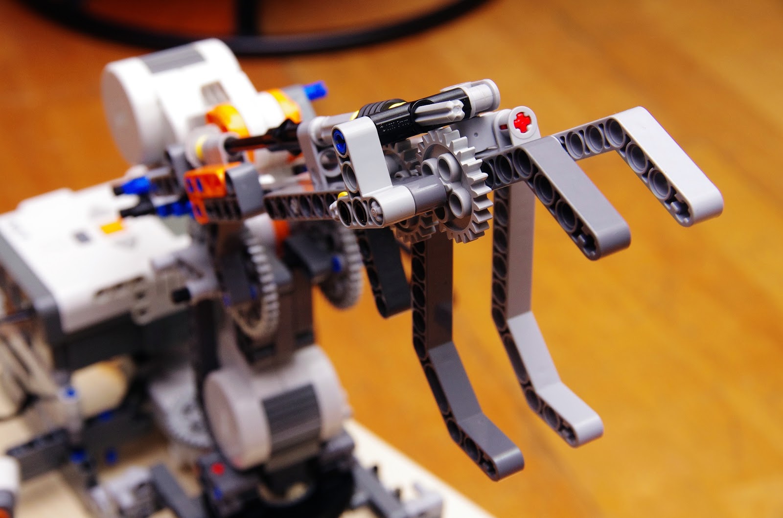 |
| 當第三顆馬達抓取物品時齒輪經過轉向帶動下個齒輪與傳動軸會產生其它方向應力讓零件慢慢位移是甚至解體,因此在組裝上必須考量結構強度與預防零組件位移措施。 |
int iTch=Motor.A.getTachoCount(); //讀取A馬達角度值
Motor.A.resetTachoCount(); //重設A馬達角度值
測試步驟:
1. Android手機與第一台樂高機器人藍芽連結並啟動NXT程式(非必要性只是測試Android手機與樂高機器人的互動)
2.光線感應器先偵測黑色與白色的反射數值當作黑色軌跡路線的判斷標準
3.當第一台NXT在軌跡路線上(PID)運行時,如果超音波感應器遇到前方12公分內有物品時,車輛迴轉180度讓後方的爪子去抓取物品,抓取物品後車輛再迴轉180度繼續在軌跡路線上前進,此時顏色感應器啟動偵測路面上是否有顏色標示。
4.當顏色感應器偵測到特定顏色時開始執行「放置物品」的對應動作
綠色:「右轉」直行一段距離放在固定位置,此時第二台樂高機器人的超音波感應器或碰觸感應器被觸動執行抓取物品然後放在固定位置(預計放在黑色路線上讓第一台樂機器人繼續抓取),如此一直無線迴圈讓兩台樂高機器人一直運作。(外加動作是BT向手機傳遞訊息如顏色)
藍色:不動作
紅色:不動作
黃色:不動作
5.當遇到「綠色」標示時第一台NXT會右轉後前進一段距離放置物品再回到黑色軌跡路線上,此時第二台NXT機器手臂的超音波感應器或碰觸感應器會偵測到有物品需要抓取,因此啟用抓取程式讓NXT機器手臂移動物品放置。
硬體與軟體
硬體組裝:用樂高零件組裝結構性與強度足夠的「履帶車輛」與「機器手臂」。
軟體設計:按照測試流程來設計程式,第一台樂高NXT動作多程式比較複雜,第二台樂高機器手臂動作固定程式碼較少。
Lejos 是架構在 Java語言下因此程式結構與延伸完整,本次程式設計運用行為模式(Behavior)因此可以把軌跡車、超音波偵測、顏色偵測等各自撰寫獨立的Class測試,最後再定義各種動作(軌蹟車、超音波、顏色感應)的優先順序一起整合運用,擺除以往把3顆馬達、所有Sensor動作與變數檢查都寫在一起有時候都不知道是那個環節出錯( Debug花費時間比寫程式還多)。
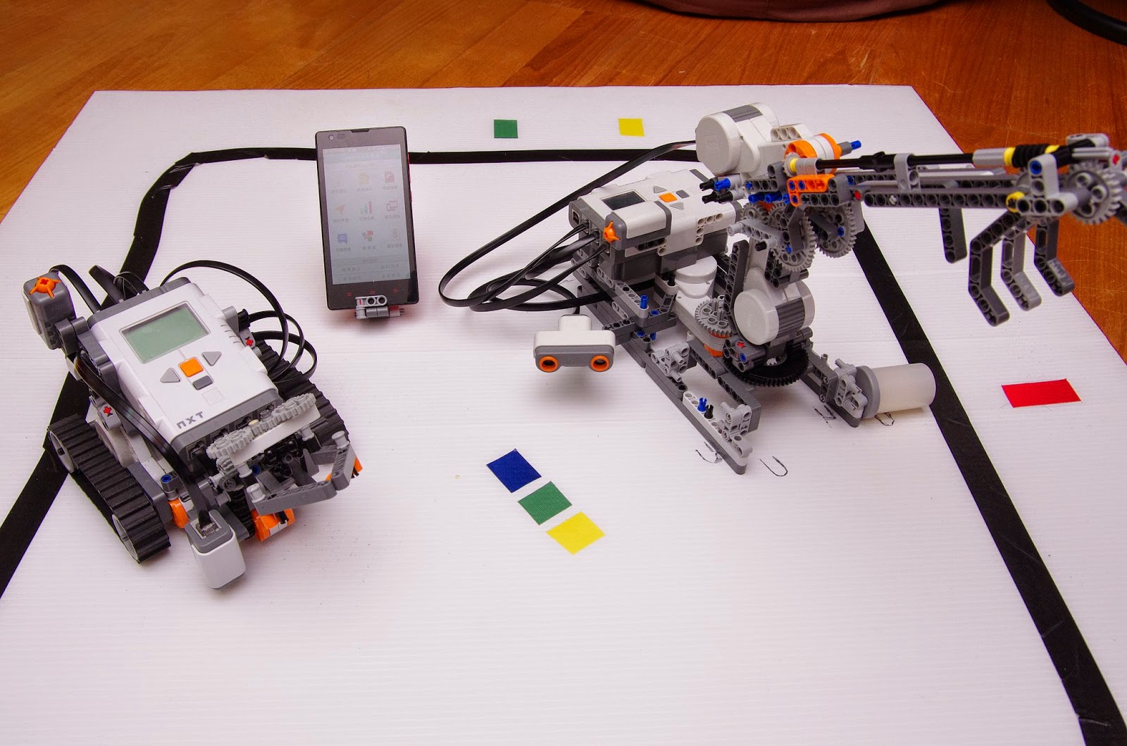 |
| DIY場地:各色膠帶 + 白色真珠板.....準備測試。 |
YouTube影片資料
訂閱:
文章 (Atom)